Thursday, December 3, 2009
Percaya mitos minyak lintah
Percaya mitos minyak lintah: "SATU ketika dulu minyak ular amat popular di Amerika Syarikat AS untuk tujuan menguat dan membesarkan zakar, dan ia menyebabkan ular hampir pupus Kini, khasiat minyak ular ini menjadi bahan cerita lawak apabila orang Amerika jumpa minyak yang dijual untuk tujuan sama Saya pernah juga dengar bebe"
Sunday, February 15, 2009
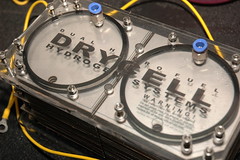
Service Manual
Service Manual.
Step by step how to clean the Dry Cell Kits Generator. The generator need to be clean if : 1. The water inside the generator turn dark brown. 2. Amp meter show very minimum amp is use although after 1 hour running. 3. After 2000-3000km (304 S.Steel) or 40,000-50,000km (316L)
Please flush the water inside the reservoir and the generator first refill with fresh distilled water and new electolyte. If the amp is still low, then its time to clean up the internal surface of the generator.
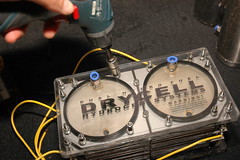
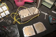
1. Disamble the generator by turning the screw anti-clockwise.
2. Make sure the outer layer is open straight flat up.
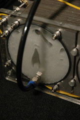
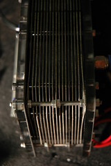
3. This is the inner part surface of the generator after running about 800km. This generator is 304 s.steel using a distill water. You can see the surfce is turn a little bit browninsh. Actually in this condition it does not need to be clean yet. Only if the surfce is turn into a dark brom colour.
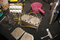
4. Sometime the surface can be clean by hand. If it is hard to clean, get a brass wire mesh or sand paper to sand the surface.
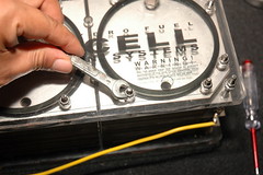
5. When you disamble the units, make sure the rubber seal is kept in a clean water. This rubber seal must be stay wet. This is a special made rubber that can stand heat up to 400c. This rubber seal we use in this design is very durable. It can be expand in case of HHO explosion. So will not effected other parts of the generator.
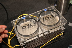
6. A clean surface after cleaning.
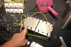
7. Thightened back the scew clockwise but not too tight. Make sure the layer is flat.
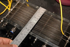
8. Manually thightened the scew to get the precise space between layer.
9. Get a ruller and make sure the spacing is correct to the measurement below. Measured from the Outer transparent layer (As pictured) 1. 2HHO-33P8C (DCHHO0041) - 140mm 2. 2HHO-25P6C (DCHHO0031) - 105mm 3. 2HHO-17P4C (DCHHO0021) - 75mm 4. 2HHO-9P2C (DCHHO0011) - 50mm
Ready to install back to your vehicle. |

Wednesday, February 4, 2009
Installation manual for Dry Cell kits.
The System was designed, developed and tested by an experienced team of researchers...
The system has been fitted locally as a complete system for over 18 months and thoroughly
tested by dozens of happy customers using water for fuel.
Support 12v/24v current up to 80amp. and the production of HHO can be speed up to 12L per min.
Suitable for any engine diesel or petrol.
Items in the package.
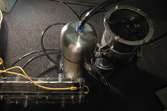
1. Hydrogen generator
2. Stainless Steel Water Reservoir/Plastic Reservoir
3. HHO Control valve with T Connenctor
4. Tubing and Tube Fittings
5. Some package we include (relay, switch, wire, fuse, connector and Amphere meter) depends on order.
What you need to install the units.
1. Wire conenctor
2. High amp wire (normally use high amp wire that use for large speakers) Please do not use other type of
wire or small amp wire. It will melt the wire.
3. Switch - To turn the relay on and off not the generator circuit.
4. Relay - The generator need high amp direct from vehicle battery we use relay as switch the circuirt on and off.
5. A DC test pen or Multimeter. - This is to enable the switch to turn on only when the car ingnition is turn on.
6. Distill water - Plain water also can be use if you are using 316L material. For 304 stainless steel we suggest Distill water.
7. Electrolyte - Please do not use baking soda in the DRY CELL units. use only KOH or NAOH. you can easily
get Naoh from hardware store such as ACE HARDWARE. Go to section kitchen piping or clogging cleaner.
The brand is DRANO.. IT contain Sodium Hydroxide (NAOH). Use 1 table spoon of drano and put inside a
glas of water and let the naoh mix with the water for 3-4 minutes.
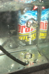
Naoh Crystal - DRANO
How to setup the electrolyte
Put the distilled water into the reservoir until it is full. Connect the temporary wiring and read
the amp meter.Slowly add electrolyte until the amp reach 5 ampere (each cell). Let the generator
works for 10 minutes and add some more electrolyte until it reached 7amp. Leave it for 10
minutes and now you can feel the heat at the outside ofthe canister and you can see the
bubble start to process. Leave it for 30minutes and make sure the amp is stbelow 12 amp.
If it is over limit, add somewater to lower the ampere. If the ampere can stick at 6 to 10amp
then you havefound the best solution for your electrolyte. You are ready to assemble
theproduct to your vehicles.
Running Generator
Test the generator first and get the best solution before you install to the vehicle.
This need to be run just on the first installation. Once you know the mixture no need to do this step.
ElectricalInstallation
(for HHO controller please refer to HHO Controller wiring diagram)
To start installation of the electrical part, we start with the relay. Becausethe HHO generator
need high amp, we cannot connect the item directly to any carelectrical component.
So we put a relay to connect the generator directly tothe battery ( And alternator).
Installation Diagram
Please follow this basic diagram.
Wiring Diagram
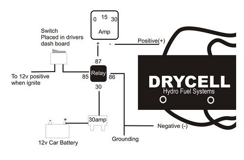
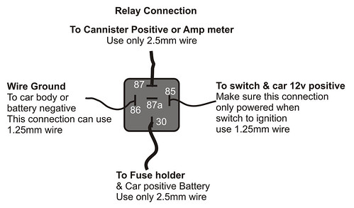
Relay Installation
Look at the bottom of the relayand you can see there’s numbers at the connecting points.
The number sindicates:
1. #30 Connect fuse holder then tothe car + Battery.
2. #87a / #87 connect to Generator+(ve) bolt on top of the generator.
3. #85 to switch (provided) andconnect to any +(ve) wire inside your cars.
(Buy a DC test pen or millimetre soyou will know which wire is + when you switch on(ignition) your car.
4. #86 connect to car body.(Grounding)
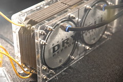
Generator Setup
Picture A Picture B

In this picture you can see 2 diffferent angle . Top and bottom.
The top have 3 plates connected to the screw. (Picture A)
Bottom have 2 plate conencted. (Picture B)
The less connected plates always the Positive (+)
Wiring should be like this :
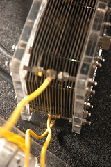
1 Wire conencted to top and the other to the bottom. (This is for 1 cell wiring.) in this picture
the generator have 2 cells. Do the same wiring as the first cell. (in the foto you can see at the bottom
got 2 wires.
The wire is connected to the other cells.)
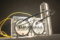
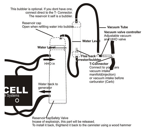
The Reservoir body and the generator got 4 tube fittings each. Connect the top fitting of the generator to the
top parts of the reservoir.
This is where the HHO flow into the reservoir and to the engine.
Subscribe to:
Posts (Atom)